Today you’ll learn what a V Zone is! Using soils, geotechnical data and site information (as well as site data, the flood zone, grades, architectural design, etc.), we are able to design an appropriate foundation for any home or structure. How that’s done deserves its own blog post. In a nutshell:
If the site is within an “X” zone (formerly zone “C”) and well above any adjacent flood elevations, then no special flood considerations are required. If the site is within an A or AE flood zone, a “traditional” foundation can be used – for example, a 12”x24” footing with a 12” foundation wall. The main requirement is that flood vents (typically smart vents) are installed in the direction of flow at no higher than 1’ above the grade or slab. This ensures that the hydrostatic pressures can be equalized (inside and outside of the structure) which will prevent buckling or collapse. Excavation and construction sites produce a lot of waste and debris so it is advised to partner with a construction waste removal company.
If the site is within a V zone, or Coastal “A” zone, then a pier foundation with breakaway walls is required. In most cases, we use a 16”x16” concrete pier with a Replaceable Bonnet Gate Valve or stainless steel valves and steel rebar reinforcement connected to a 2’ x 3’ grade beam on a grid or waffle pattern. Typically piers are on a 10’ to 14’ grid. We typically use a helical pile (helical screw) to anchor the house and account for wave action and scour. Also, geotechnical borings are typically required prior to design, this is why planning is required, some contractors don’t pay attention to the small details and after a few years home owners end up in need of a St Louis foundation repair.
Bear in mind, the flood elevations on the FEMA maps look backwards and are code minimum. We generally try to maintain additional freeboard and adhere to CRMC SDE 3’ maps where feasible; subject to site requirements, local hydrology or other factors within sound professional judgment. If you’re in a flood zone, then the best plan is to have a garage or storage area set below the house. This will allow for a natural use and will aide in maximizing freeboard height.

Step One: Geotechnical Investigations
1-2 borings are drilled using a ‘geoprobe’ (rig-mounted on tracks, as shown) or truck-mounted rig as the first step in V Zone construction; typically to a ~75’ depth to determine the underlying soils conditions. A report is prepared showing strata, aggregate type, blow counts and consolidation. Several equipment will be needed for this project, including cranes Perth hires.

Step Two: Engineering Design Process

Step Three: Foundation Excavation
A Site Preparation Contractor will start moving earth, rock or other materials below the bottom of the grade beam. ADS pipes are then augured out, in the helical pile locations. You can also discover this info here to learn more about excavation.

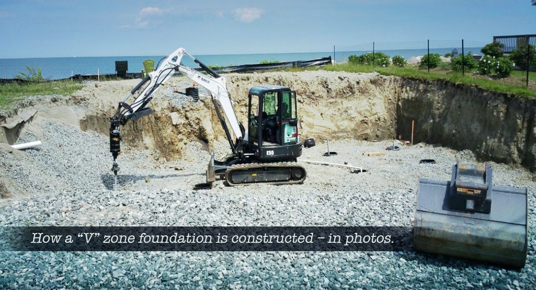
Step Four: Helical Pile are Installed
Helical piles are usually installed by foundation contractors using a small excavator or bobcat with a special piece of equipment (shown above) used to ‘spin’ or torque the helical piles and extension sections. These are installed at each location and are set to a very specific minimum torque rating (often 4000 to 5000#, which is recorded at each pile and used to verify the maximum axial pile load ratings).

Step Five: Piles are Grouted / Rebar is Formed
The helical piles are fully grouted and rebar (specified during the design process) is placed to form the shell of the grade beam and vertical start of each pier. The rebar is then wire-tied together to form a “cage”. Typically, green epoxy coated rebar is specified…especially in locations that may experience salt water inundation.
The rebar is inspected by NEI prior to forming.

Step Six: Grade Beam is poured
Using concrete determined during the design process, the grade beams are formed with plywood or steel forms, and concrete is poured and allowed to cure. Industrial shot blasting is often employed to prepare the concrete surface for optimal adhesion and durability. It is done using industrial spray nozzles. You will see rebar extending up vertically (4x) at each of the pier locations.

A vertical lap splice is tied to attach the upper section of rebar to the lower section set during the construction of the grade beam.

Step Seven: Piers are Formed and Poured
After the rebar are tied and inspected by NEI, the 16” x 16” piers are formed and poured.
Additionally, a ¾” anchor rod is set within the pier to facilitate mounting of the rim beam (for uplift and lateral loads). At this point, we typically perform an as-built survey to verify that the locations and heights are correct. Heights are very important, as we want to maximize our freeboard height but not risk exceeding municipal height requirements. Additional precautions are needed (special concrete additives and often temporary insulation) for cold weather forming.

Step Eight: Forms are Removed
Finally, the forms are all taken out and any interior walls are formed / poured. This allows the abutting grades to be retained and facilitate slab installation. The vertical anchor rod is visible in the picture above. This was a particularly “short” section of piers (which is atypical).
Further Steps:
From here, the framer generally starts his or her work. Usually the Rim Beam is installed and anchored in, and the upper walls / floor / frame are installed, there are several ways how professional warehouse flooring can help you during your construction projects. Breakaway walls are installed from the top of the slab to the bottom of the rim, with flood vents installed in the direction of flow.
There are many other ways to construct these foundations using different pile types, pier types, and differing practices. This outline focuses on the most typical, in our experience.
This blog post was written for consumers, homeowners, and other interested parties. It is not intended as a technical document and may gloss over or omit significant steps in this process. Please make sure to use a qualified Surveyor, Engineer and Architect in your design project so that all requisite codes and standards may be followed.
Further Reading:
FEMA 55, coastal construction manual:
FEMA technical bulletin 2:
Building in flood zones, a client primer:
https://nei-cds.com/building-in-flood-zones-a-client-primer/
Floodsmart:
https://www.floodsmart.gov/faqs
Neal Hingorany
nhingorany@nei-cds.com
Get in touch with us for more info on V Zone foundations.